Choosing The Air Conditioning System
Air Conditioning
CHOOSING THE COOLING SYSTEM
The cabinet heat exchange must first of all be calculated in order to identify the most appropriate cooling system.
HEAT EXCHANGE CALCULATION
Calculating the heat load to be dissipated represents the essential step when choosing a cooling system, and four factors should be considered: the heat dissipated by the equipment inside the panel, the temperature in the room where the panel is installed, the temperature to be maintained inside the panel, the control board sizes and set-up conditions.
Concerning the quantity of heat produced by the inner components, the data on the technical sheets of the components themselves must be checked and evaluated. No need to say that the possibility that several units may work simultaneously should be taken into consideration when making this calculation.
Also, as already mentioned, the temperature of the room where the electrical cabinet is installed must be carefully evaluated.
In fact, an exchange takes place among the panel surfaces and the environment. If the outside temperature is lower than the inner one, the heat is transferred from inside to outside, and must be subtracted from the heating load produced by the components; if, on the contrary, the outside temperature is higher than the inside one the opposite will occur, hence the heat absorbed must be added to the heat dissipated by the equipment. On s/s surfaces, 5.5 W/
m2K are transmitted per each square meter of cabinet surface.
The calculation of the over-temperature inside the cabinet must comply with CEI 17/43 standard, according to the cabinet operating conditions.
The relevant calculation sheet in Microsoft® Excel format is available for easier calculation of the thermal exchange according to the above mentioned standard.
An approximate calculation is however possible following the method below:
Type of installation (data derived from Table 3 of CEI 17/43 standard)
KEY
| L = Cabinet width (m) | H = Cabinet height (m) | P = Cabinet depth (m) |
| Detached, exposed on all sides | Back panel close to a wall | Left side close to a wall |
| Right side close to a wall | Left side and back panel close to a wall | Right side and back panel close to a wall |
| Right and left side close to a wall | Embedded with sides and back panel close to a wall | Fully embedded with top side covered |
The following formula shall be used to calculate the cooling or heating power:
Pe = PV –( k x Ae x Δt)
where Ae is the cabinet actual surface derived from Table 1 above, Δt is the algebraic value of the gap between the required inner temperature and the cabinet outside temperature and k is the heat transmission coefficient (approx. 5.5 W/K m2), Pv is the actual power dissipated by the equipment inside the cabinet, while Pe is the required cooling or heating power.
Reference to Table “HEAT PRODUCED COMPARED TO ABSORBED POWER” is possible for an approximate calculation of the PV power.
|
Heat produced compared to power absorbed |
|
| Electric/electronic component |
Heat produced in W |
| Trasformers – Inverter – Drives |
5% of the power |
| Feeders of electronic components |
10% of the power |
| Coils of relays and counters |
5% of the power |
| Glow lamps |
95% of the power |
| PLC |
150W |
| Numerical controls |
200W |
The data in the table are approximate mean values that require checking according to the equipment actually in use
The following example can facilitate understanding :
In a control board with a total surface of 5.3 m2 have been installed a 15000 W transformer running at full capacity, a 1000 Watt lamp, a PLC and a 20000 W inverter running at 80%. Basing on the table, we will have the following total load:
Trasformer 15000 x 5 = 750 W
100
Lamp 100 x 95 = 95 W Total power transformed into heat PV = 1795 W
100
PLC = 150 W
Inverter 2000 x 80 x 5 = 800 W
100 100
Assuming that the above panel is installed in a room with 40°C temperature and that its temperature is kept at 30°C (-10°C), these data must be are related to the total surface of the panel itself.
The thermal power transmitted to the inside will be as follows:
5.3 x 5.5 x -10 = -291.5 W
The total thermal load will be equal to
Pe = 1800- (-291.5)= 2091.5 W
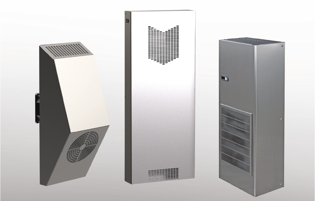
When the irradiating surface of the cabinet cannot dissipate the thermal load produced by the equipment inside it, the most appropriate cooling system between conditioning and ventilation has to be chosen.
Air conditioning
This cooling system is particularly recommended when the temperature inside the Panel has to be maintained equal to or lower than the temperature outside it. To safeguard its reliability, the conditioner should be carefully sized, in order to select a model properly sized to keep the temperature within acceptable limits even in the worst conditions, while avoiding over-sizing. The room temperature must therefore be related to the Panel inside temperature, to obtain the so-called correction factor, i.e. the data necessary to determine the conditioner rated yield. Graph below can help to determine this factor:
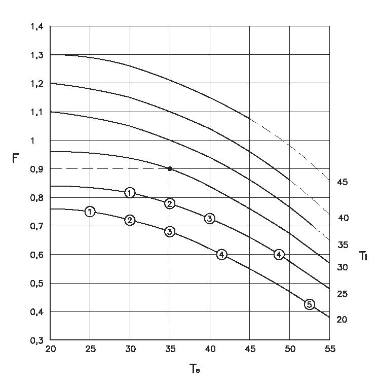
Where:
- The room temperature is shown on the axis of abscissas as Te
- The correction factor F is shown on the axis of the ordinates
- The curves correspond to the temperature inside the Ti board, the dashed section indicating the area that can the air conditioner can cover only for short,
- The circled numbers indicate extreme work conditions, as a function of the percentage of the outdoor relative humidity:
1 – 80 %
2 – 60 %
3 – 40 %
4 – 30 %
5 – 20 %
Setting the temperature inside the board to below the values indicated, condensate forms on the electric components as doors are opened, since the dew point is reached.
Example of correction on the yield:
For outside temperature of 35°C and 30°C inside, the correction factor is 0,9. Therefore, to achieve 1.000 W in these conditions, an air conditioner featuring a rated yield (L35L35) of 1.000 / 0,9 = 1,112 W is required. Viceversa, an air conditioner having a 2.000 W rated yield, gives 900 W in these conditions.
Once this value is determined, the actual yield of an air conditioner can be set according to the following formula:
Air conditioner rated power = Required Cooling Power
Correction Factor
For example, for a 45°C outside temperature and 35°C inside one, the correction factor is 0.85. This means that, in those conditions, an air conditioner with 1000 W rated power yields 850 W and that an air conditioner featuring a 1176 W (1000 W / 0.85) rated yield is required to obtain a 1000W yield.
When the use of an air-cooled air conditioner is decided, the following must be taken into consideration:
- The outside of the air conditioner must be uncluttered, to avoid a poor yield of the same or even the compressor stoppage following the tripping of the protection device.
- A standard air conditioner can run with minimum outside temperature 20° and maximum 55°C
- The board inside temperature must be maintained between 25°C and 45°. Higher temperatures can be dangerous for both the air conditioner and the components inside the board, while lower temperatures can give rise to condensate on the components following the door opening.
- Certain voltage and frequency values are indicated for each air conditioner, along with the corresponding permitted allowances.
We recommend to never exceed such allowances, to avoid jeopardizing the equipment reliability and functionality.
- Always check for the presence of particular substances in the air, which might damage the materials the conditioner is made of. Also advisable check for the presence of any source of heat close to the cooling unit, its possible exposure to atmospheric agents and the presence of stray currents which may cause corrosion. Also, make sure the air does not contain oil or solvent fog, which might damage the standard polyurethane filters.
- Air always contain some steam, and the steam contained in the air inside the board to be conditioned condensates on the cold battery of the conditioner itself. If the cabinet is tight to the outside, once all this steam is removed, no more condensate will form. If, in contrast, the cabinet is open (even in case of small openings) water will form continuously and must be removed through the pipe the air conditioner is equipped with. This tube must be free from clogging and have no air-traps, to avoid condensate from entering the control board after a certain time. Also, a microswitch should be provided on the door of the board, to automatically stop the conditioner running, thus avoiding most of the cooling power from being dissipated to condensate the steam. It is however advisable to not open and close the doors continually, otherwise the compressor inside protection could stop its running.
VENTILATION
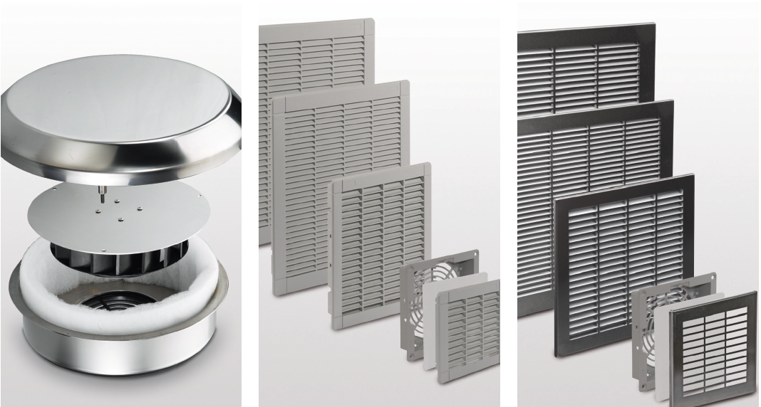
Ventilation
Cooling system recommended when the outside temperature is constantly lower than the inside one. Proper sizing of the fan requires good knowledge of the heat power to be dissipated (see THERMAL CALCULATION Schedule), as well as the difference between inside and outside temperature, while the value of the fan minimum air flowrate will be derived from the chart.
A grid with fan must always be matched with a grid without fan.
This cooling system offers several advantages: easy installation (drilling the cabinet according to the template supplied is all you need to do), limited maintenance and cost much lower than the other refrigerating systems.
Troubles and damages can be avoided:
• Making sure the outside temperature is always lower than the inside one
• Cleaning the filters regularly, and replacing them, if the need be (which can be done also while the fan is running)
• Choosing a fan slightly oversized compared to the theoretical calculations: a flow greater than required will cause no damage while providing a certain safety margin.
On request, grids and fans can be supplied pre-assembled on control panels.
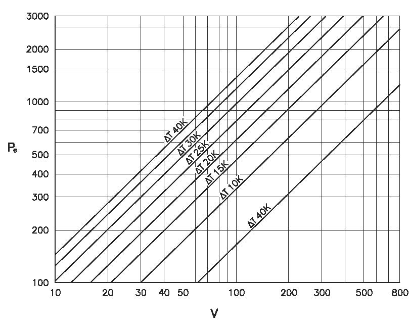
Pe = Dissipated thermal power as Watt
V = Air flow (m³h)
* The following is to be determined in advance:
– The thermal power dissipated by the electric equipment
– The maximum temperature admitted inside the cabinet
– The maximum room temperature expected outside the cabinet
• Calculate ΔT as the difference between the two temperatures
• Cross the horizontal line corresponding to the dissipated thermal power with the diagonal of temperature difference (ΔT). The crossing point between the two variables determines
a vertical line corresponding to the air flow in m3/h necessary for the dissipation required.
• Choose the suitable fan.